Technical Research and Model Design
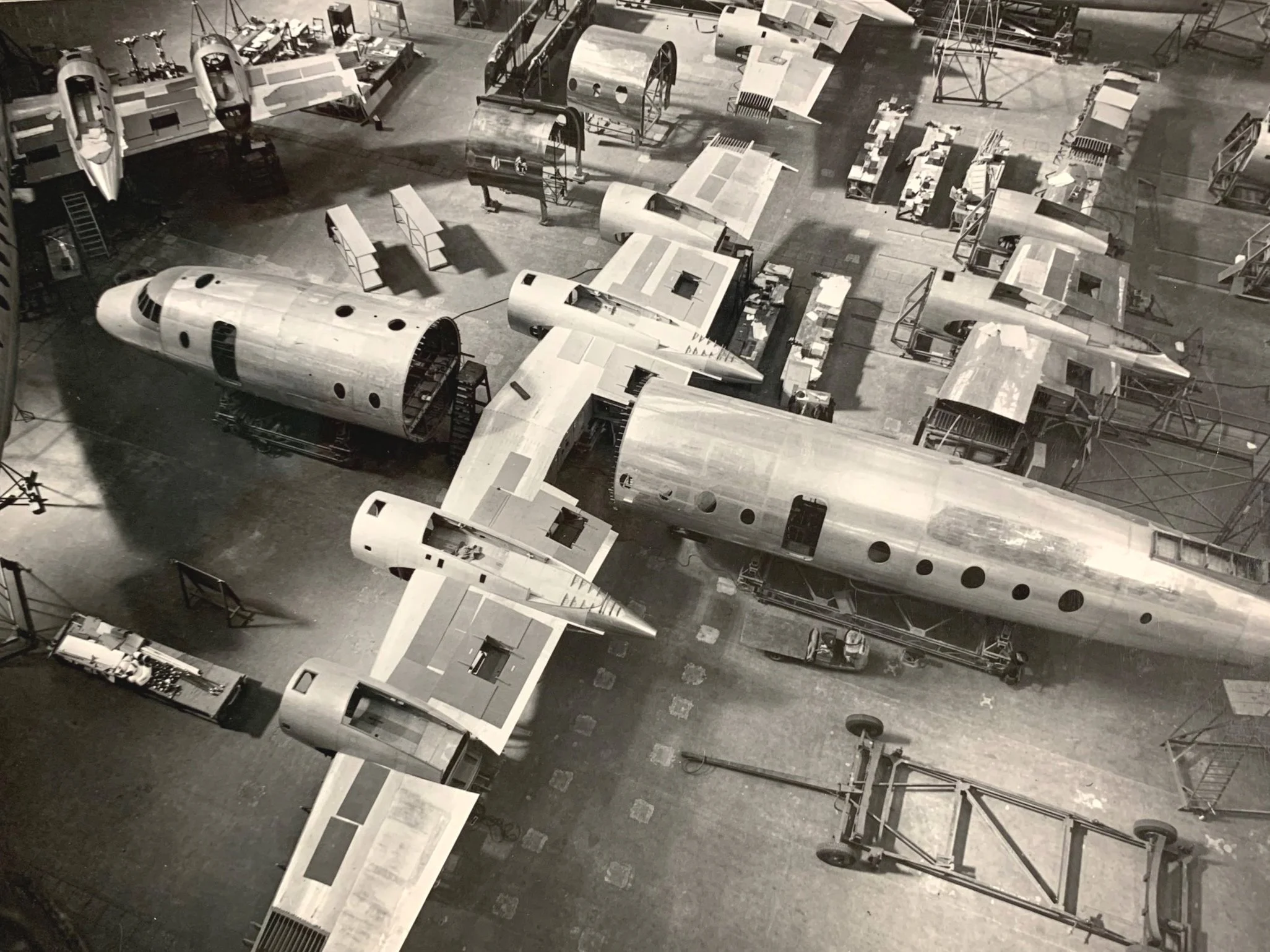
From Public Records Office Northern Ireland D4474/2/249 Image ref. T175/1371
While the internet is an invaluable research tool, it's important to remember the wealth of information available in libraries, archives, and museums. Researching the Britannia took me to locations across the UK, including Belfast (Public Record Office of Northern Ireland), Bristol (Aerospace Bristol), Farnborough (National Aerospace Library), Liverpool (Britannia Aircraft Preservation Trust), Heathrow (British Airways Heritage Collection), Imperial War Museum Duxford, and RAF Museum Cosford—a total journey of 2,032 miles (3,270 km).
Having gathered extensive information in the form of photographs, documents, books, manuals, and measurements, I faced the challenge of starting my largest and most complex model to date. After careful study of the available material, it became clear that a numerical approach would be the most effective. I began with the fuselage.
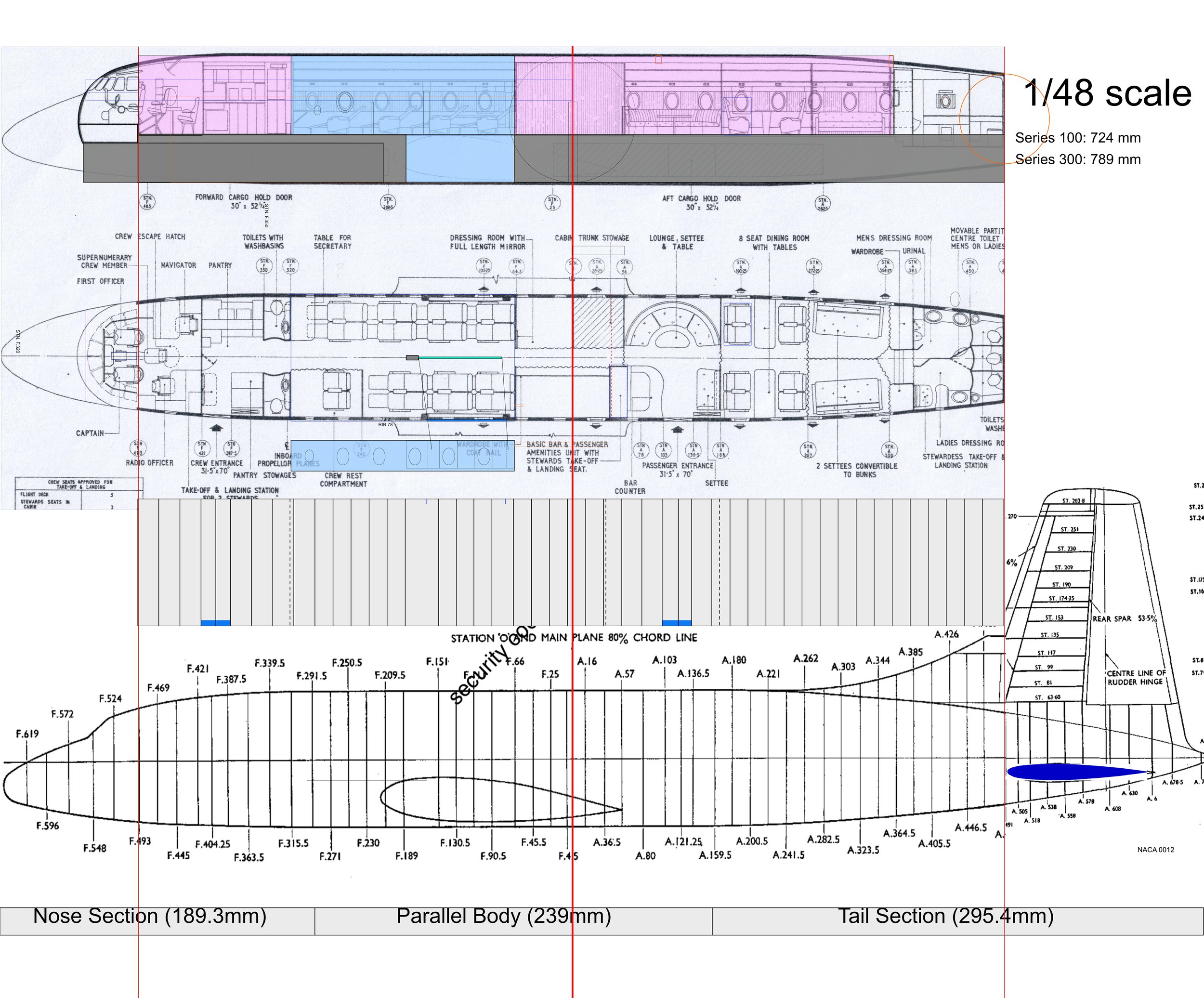
Study of fuselage frame stations with datum line in red. Light blue denotes centre section selected as basic building block for the model.
Frame station ‘0’ (the datum) for the Britannia 102 was located at the intersection of the fuselage centerline and the 80% chord line of the wing. All frame stations were actual measurements in inches, prefixed with "F" for stations forward of the datum and "A" for those aft. For example, the bulkhead at the rear of the flight deck, at station F.493, is 493 inches forward of the datum. To simplify calculations, I created a spreadsheet listing all the fuselage frame stations and divided each value by 48 (the scale factor). The spreadsheet calculations were then visualised int the form of the grey rectangle as seen in the illustration above. This way I was able to confirm the correctness of the plans I would use for the model.
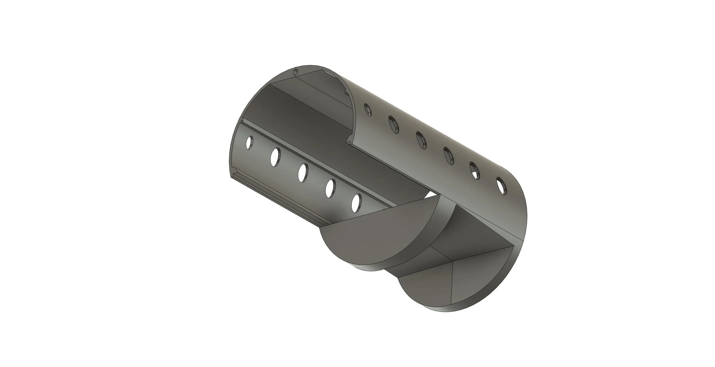
Autodesk Fusion 3D design of the model’s main component: The fuselage centre section.
The next key challenge was designing a robust yet manageable fuselage that would also accommodate interior lighting and cabin details. While the real aircraft’s manufacturing methods provided inspiration, scratch-built models are inherently different. I decided to use the cabin floor as the primary structural component, designed to slide within the upper and lower fuselage sections. Secondary support would be provided by 2mm Albion Alloys square tubes along the top. This initial design encompasses frame stations F.66 to F.320 and includes provisions for integrating the wings with the fuselage.

The Remaining fuselage as designed in Autodesk Fusion spanning from stations F493 to A491.
Every scratch-built model presents unique challenges dictated by the aircraft's design and shape. For the Britannia, the cylindrical fuselage strongly pointed towards 3D printing as the ideal construction method. Building upon the successful 3D printing trials conducted on my Empire flying boat model, I was able to significantly increase the proportion of 3D printed components in the Britannia design. However, my limitations as a designer became apparent when attempting to model the nose section. At the time of writing, the nose and canopy are planned to be created using vacuum forming.