Detailing the Britannia Cabin Interior
Imagine stepping aboard G-ANBG. While the core elements – beige wall linings, wavy white and red curtains, and the plush blue carpets – echoed the standard BOAC cabin, this aircraft was a world apart. Its VIP status was evident: luxurious, fully reclining Microcell Ideal twin passenger seats, a sophisticated lounge complete with a cocktail bar, an 8 seat dining room, private dressing rooms, a spacious wardrobe, and even dedicated crew rest areas. Passenger compartments were discreetly separated by elegant beige curtains, while the crew quarters were likely cloaked in a more subdued shade of blue.
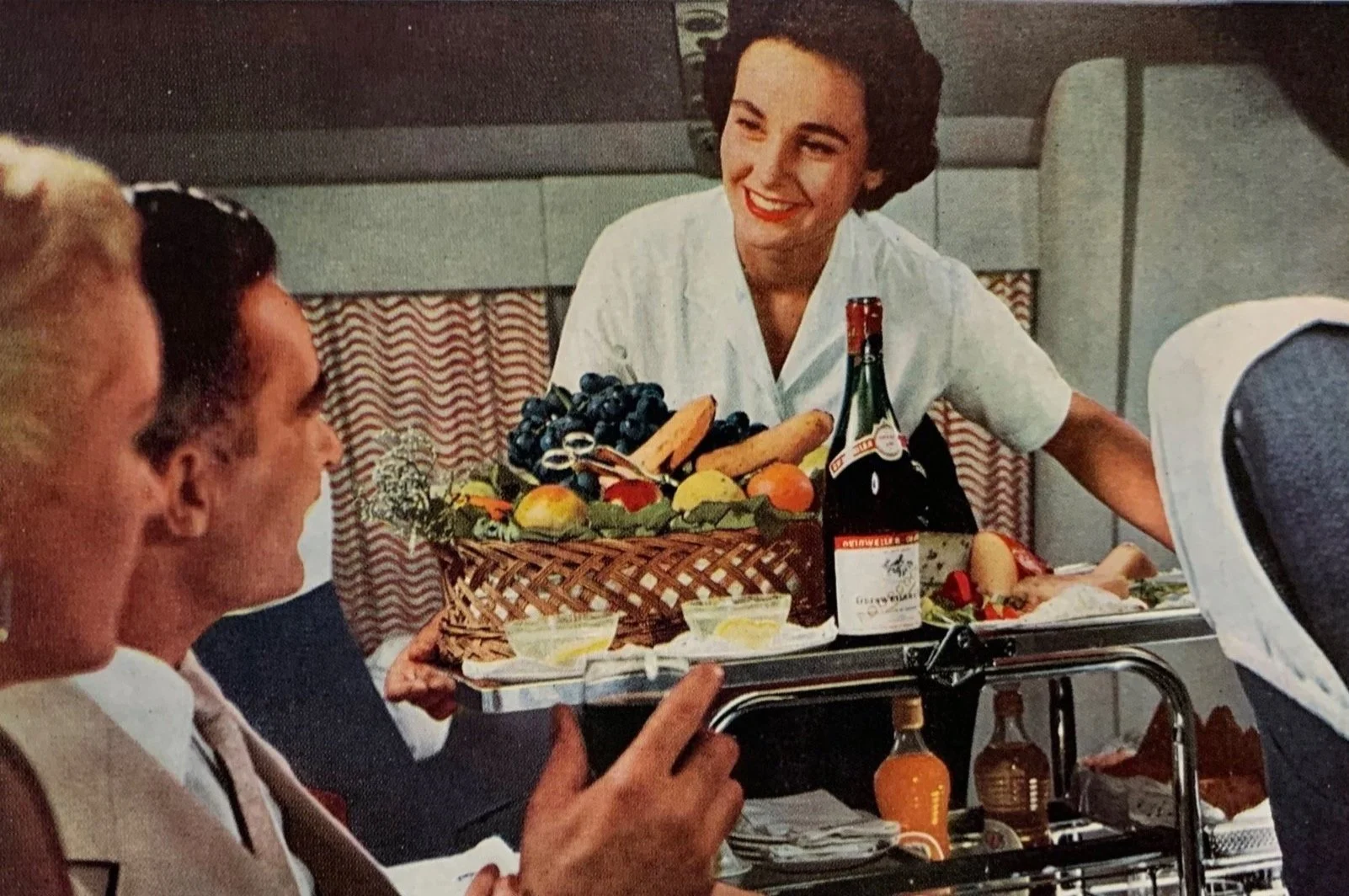
From promotional booklet: ‘Fly to London by… B.O.A.C Britannia’ . (Source: British Airways Heritage Centre)
To recreate this opulent interior in my model, I began by covering the ceilings and sidewalls with thin sheets of 0.25mm styrene plastic. In the centre section, I replicated the prominent wing spar frames, normally concealed beneath the cabin's upholstery, by using styrene plastic. To accommodate the later installation of interior partitions, I created recesses in the styrene wall coverings.
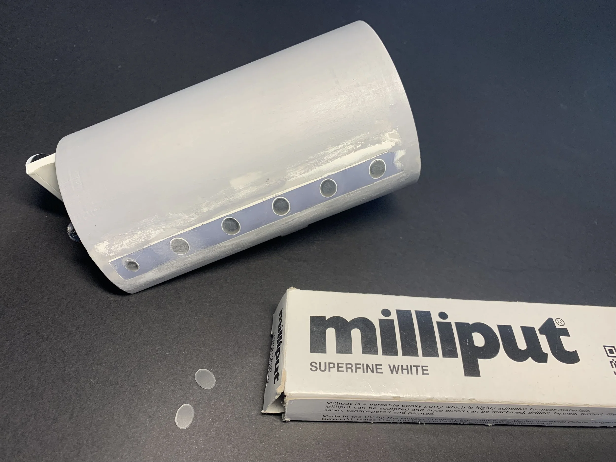
While 3D-printed ABS is ideal for producing larger volumes, it lacks the necessary precision so I opted for 3D-printed resin for the window rows. I consequently removed certain sections from the original and substituted them with 3D printed resin strips designed in such a way to later accommodate the individual windows.
To ensure their condition during the construction process, I covered the 0.5mm transparent plastic with vinyl masking film prior to cutting with a Cricut Maker machine. This layer protects the transparency from cyanoacrylate glue used for attachment and the Milliput epoxy filler for blending the windows with the fuselage. The Vinyl masking film also allows for careful sanding and the application of multiple layers of Mr. Surfacer primer without damaging the delicate window surfaces.


Illuminating the Britannia Part 1:
A tale of LED strips & ingenuity
Interior lighting in aircraft models is very uncommon. However, with the intricate detail of my scratch-built models, I strive to offer viewers an immersive glimpse inside the passenger cabin and flight deck. While I've worked on various lighting configurations in past projects, the Britannia presented a unique challenge.
Having considered my options I decided that LED strips would be the most feasible approach that would also give the most impressive and scale effective result. Yet, their fixed lengths posed an immediate obstacle, requiring meticulous planning to install the strips at specific sections within the two-piece fuselage halves.
The installation of the strips needed to go through the fuselage spar frames and the various passenger compartment partitions. To overcome this hurdle I incorporated cut-outs into these elements, allowing for a relatively easy insertion at their appropriate locations.
Connecting the lighting across the fuselage halves demanded a clever solution. I opted for miniature connectors, enabling me to work seamlessly on each half independently while ensuring a secure and permanent connection upon joining.
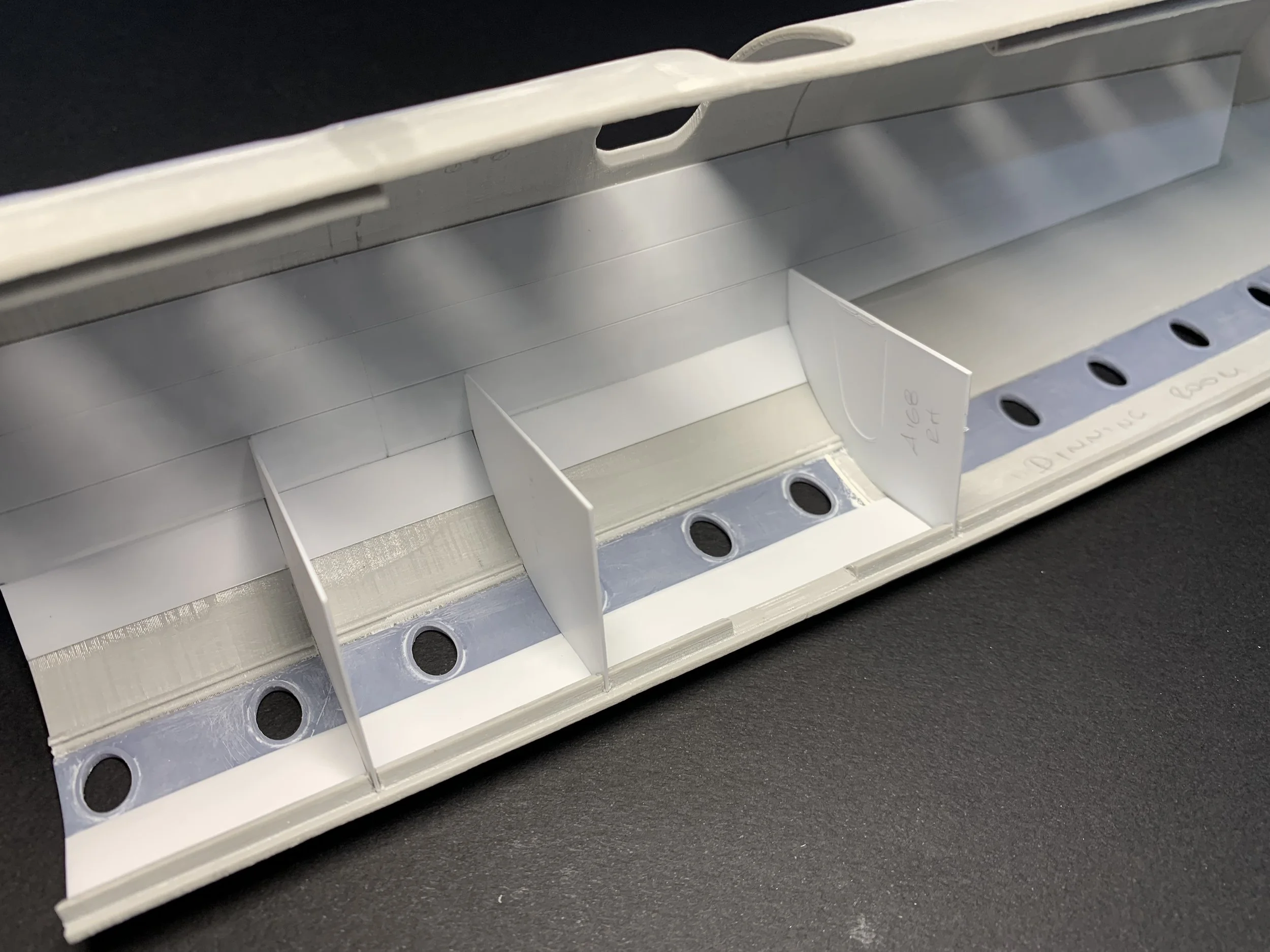
Ceiling lights electrical installation: LED strips in increments of 50mm in forward and aft fuselage section. The LED strips I used came with pre-soldered cables and were either 50mm or 200mm in length.

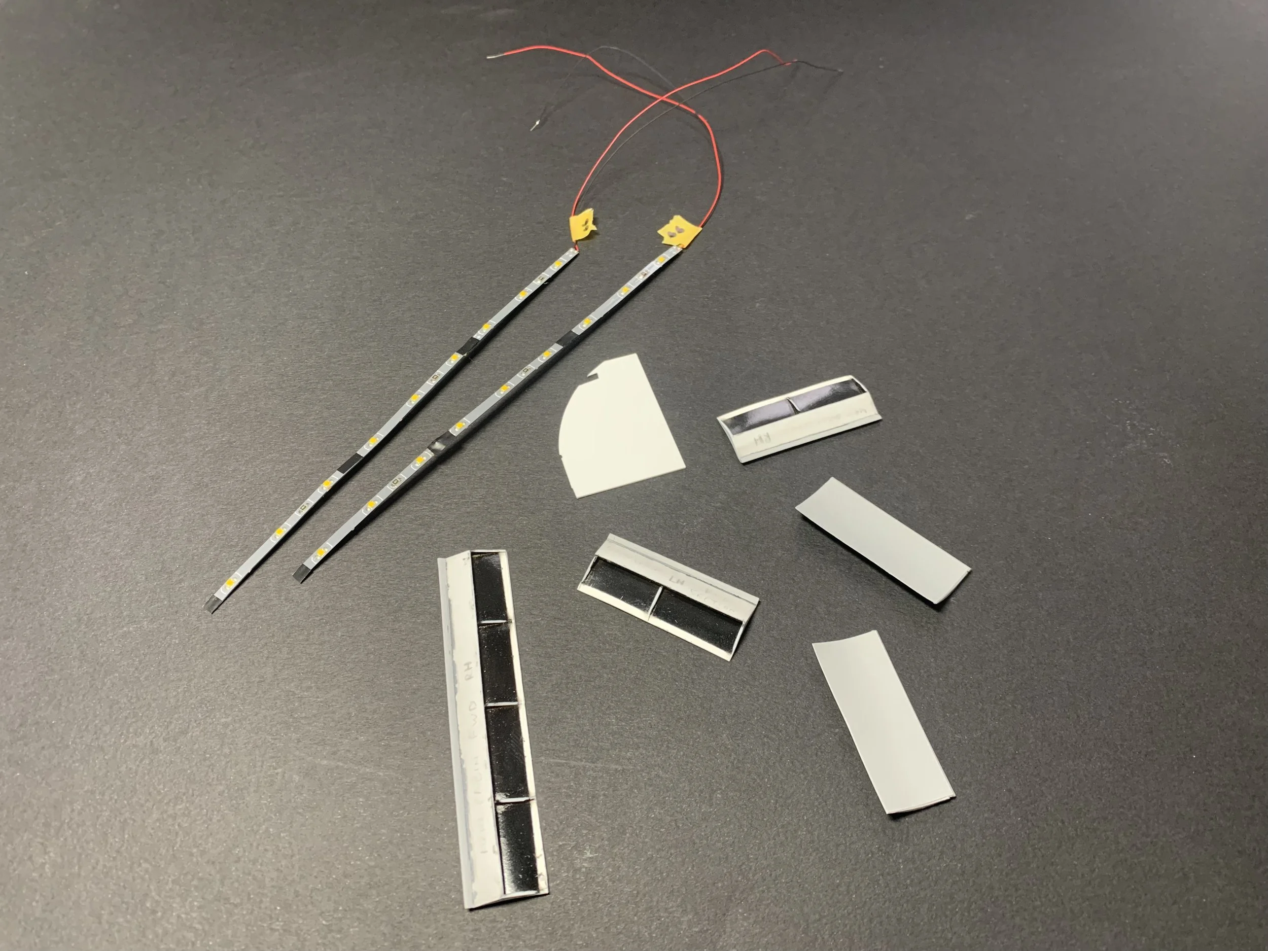

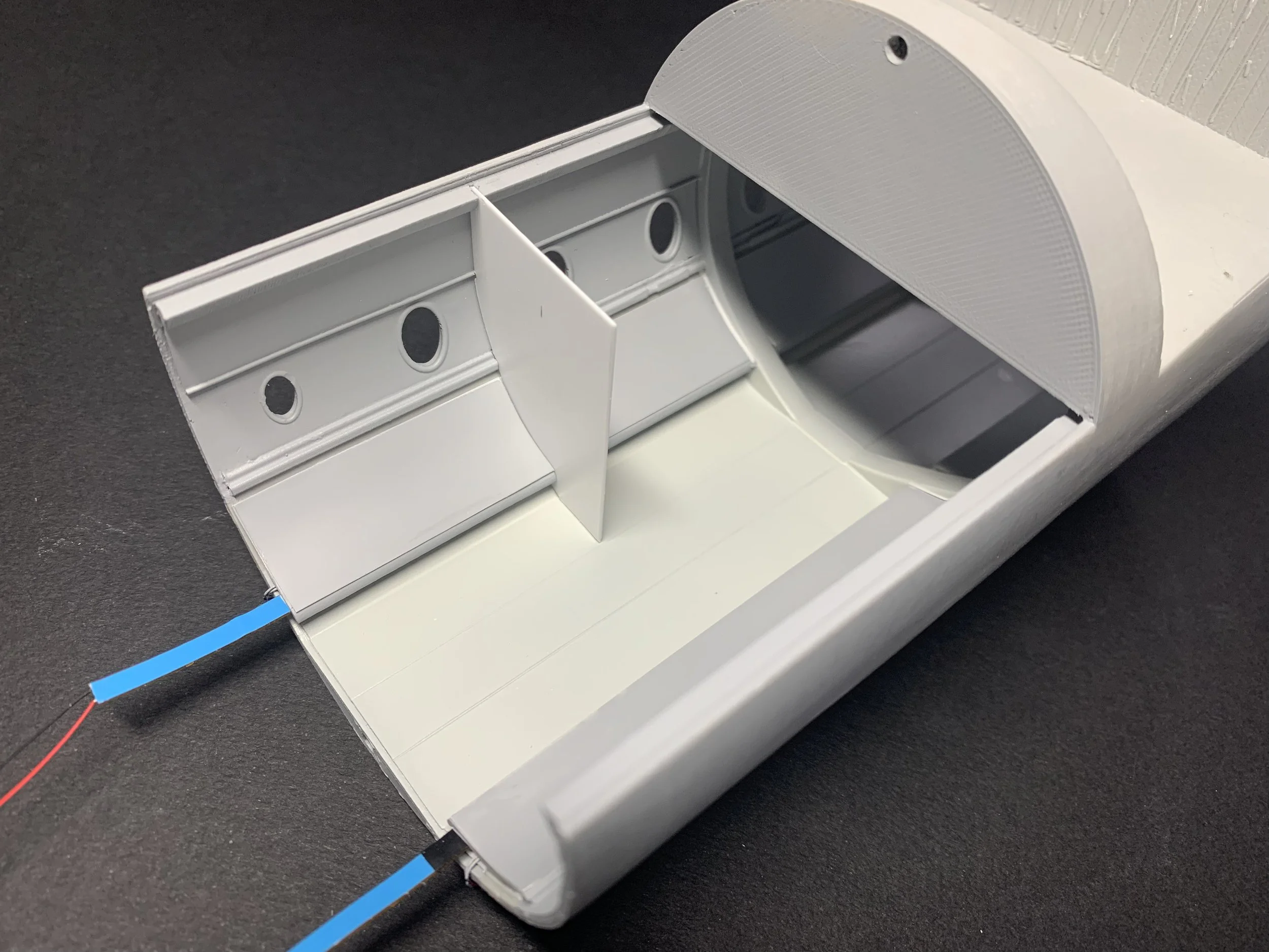
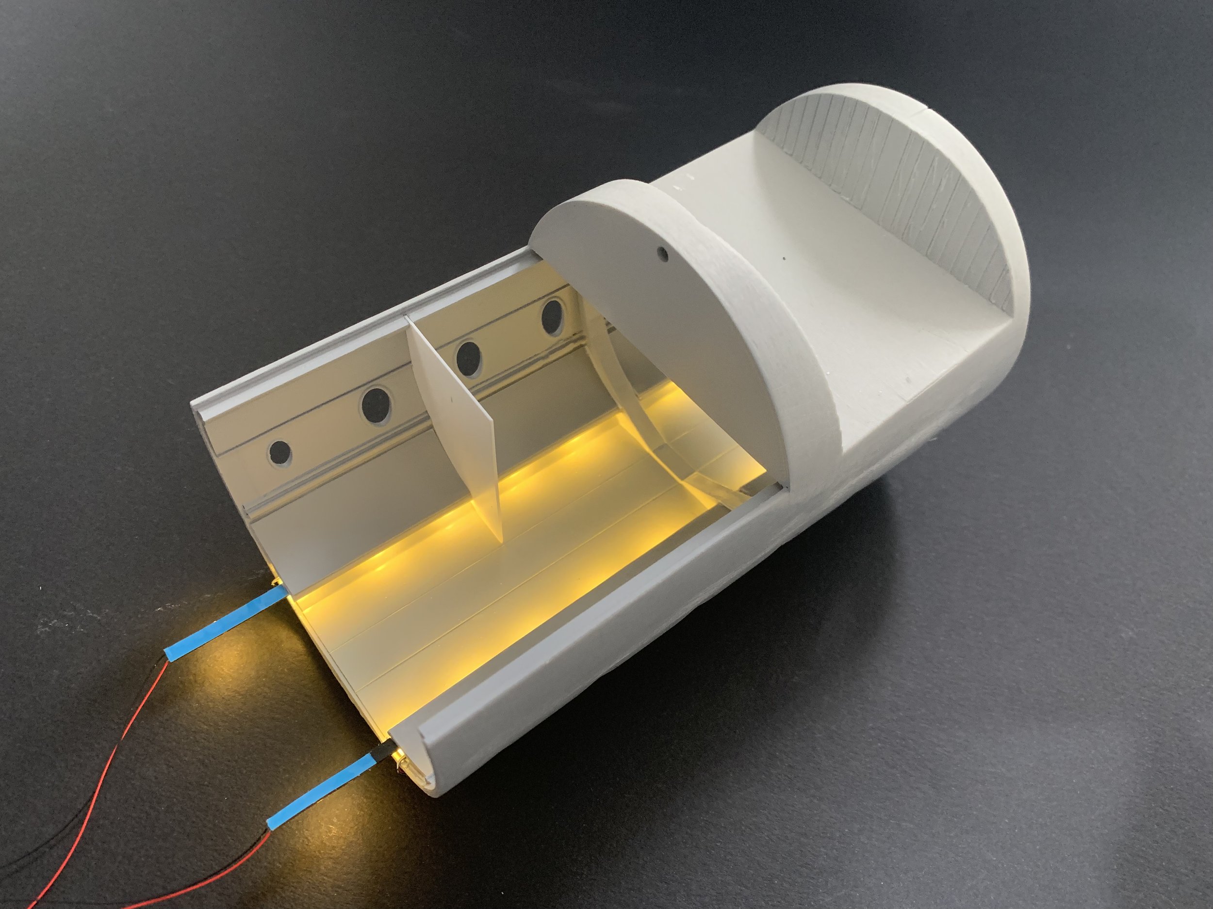

The ceiling light cabin linings were crafted from thin styrene sheets (Photo No. 1). To prevent light leakage, I painted the inside with several coats of black acrylic paint (Photo No.3). The LED strips were then carefully slid through the front fuselage section, followed by the attachment of the linings straight onto the self adhesive backing of the strips. I also used cyanoacrylate glue to fix the linings into a recess above the window rows (Photo No.4). The aft fuselage section was modelled in a similar manner.
To connect the two halves, I soldered the ends of the aft fuselage LED strips to male miniature connectors on each side. Corresponding female connectors were used to route the aft fuselage cables forward, ultimately converging at another female connector that also received the cables from the forward LED strips. All connections within the forward connector were then sealed with silicone and concealed within the forward lavatories. To prevent any light escaping from the forward-most LEDs (which I could’t cut due to the 50mm increment limitation), they were discreetly housed within the black-painted interiors of the lavatories.
Note: These LED strips are illuminated by connecting to a 9 Volt DC supply. Model Railway shops have a variety of miniature lighting products and solutions.
Curtains & Partitions
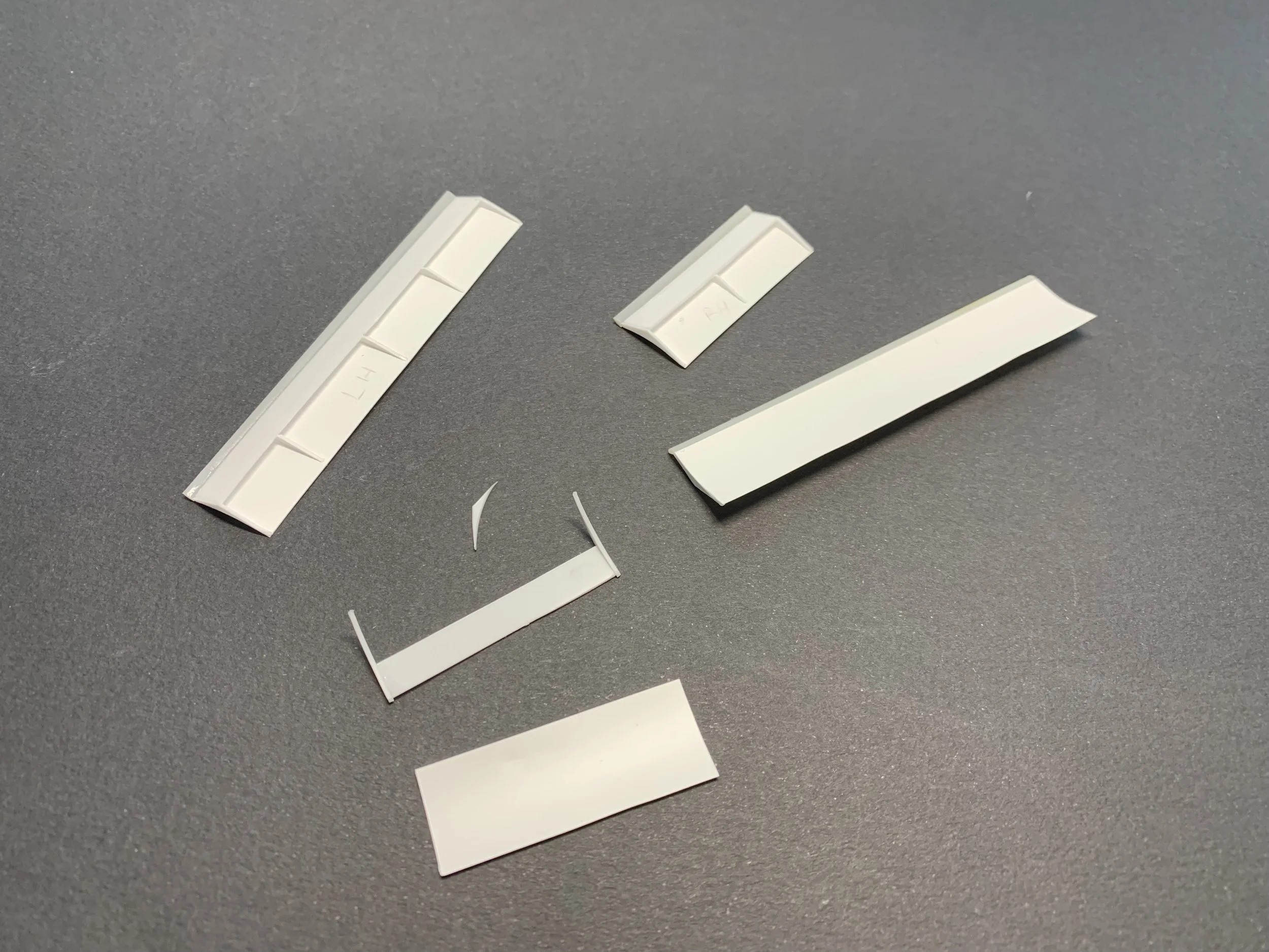
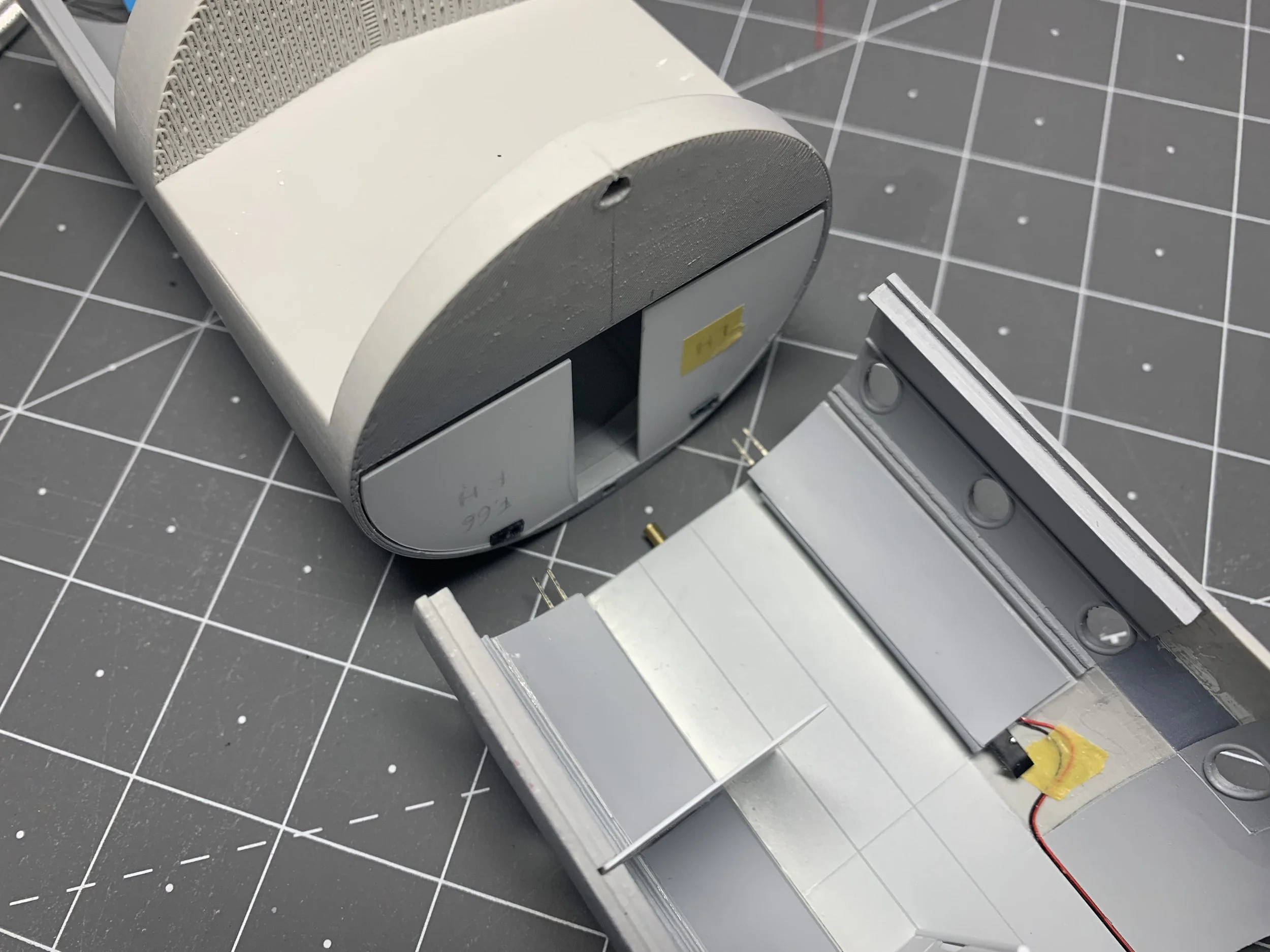
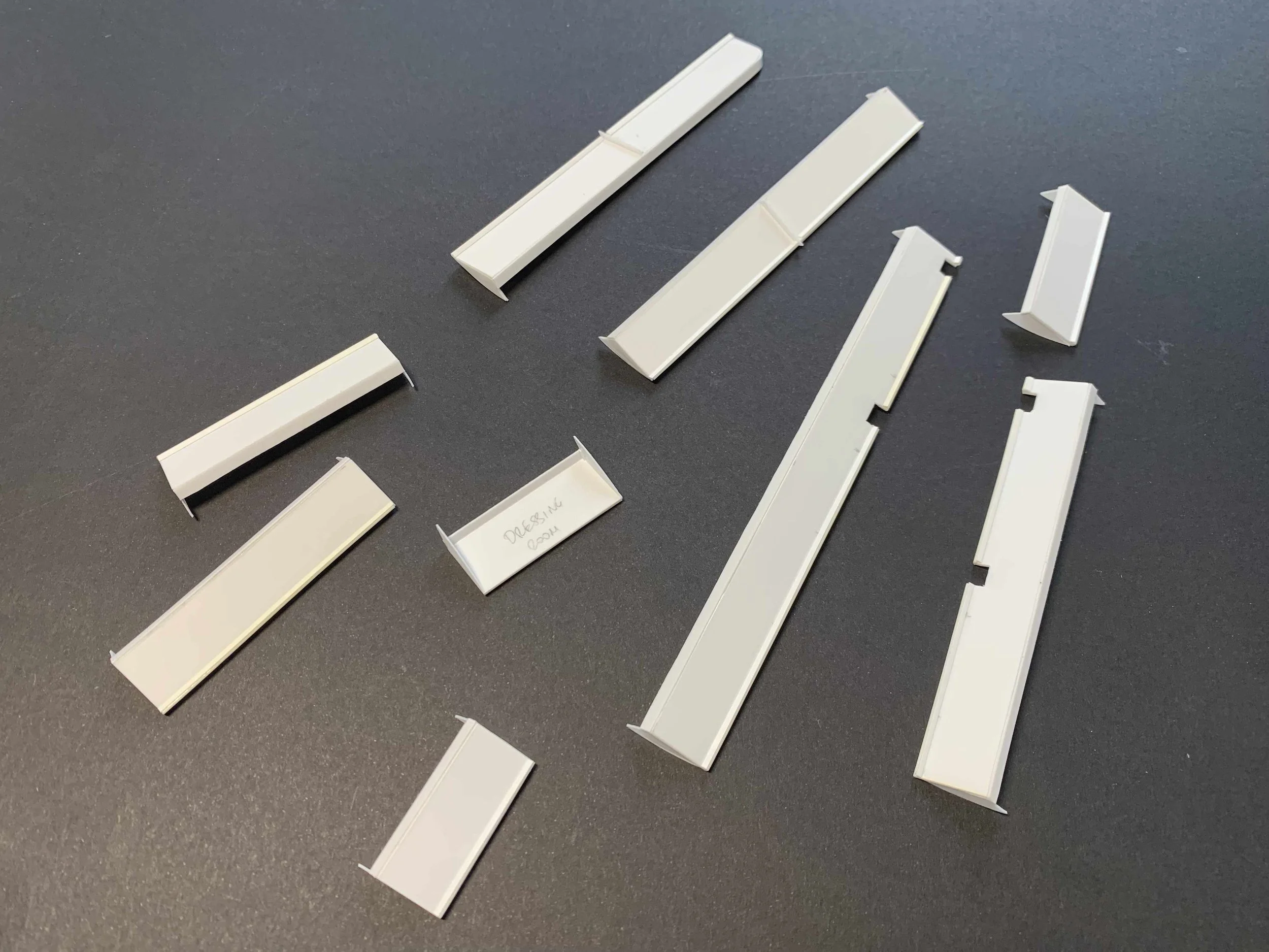
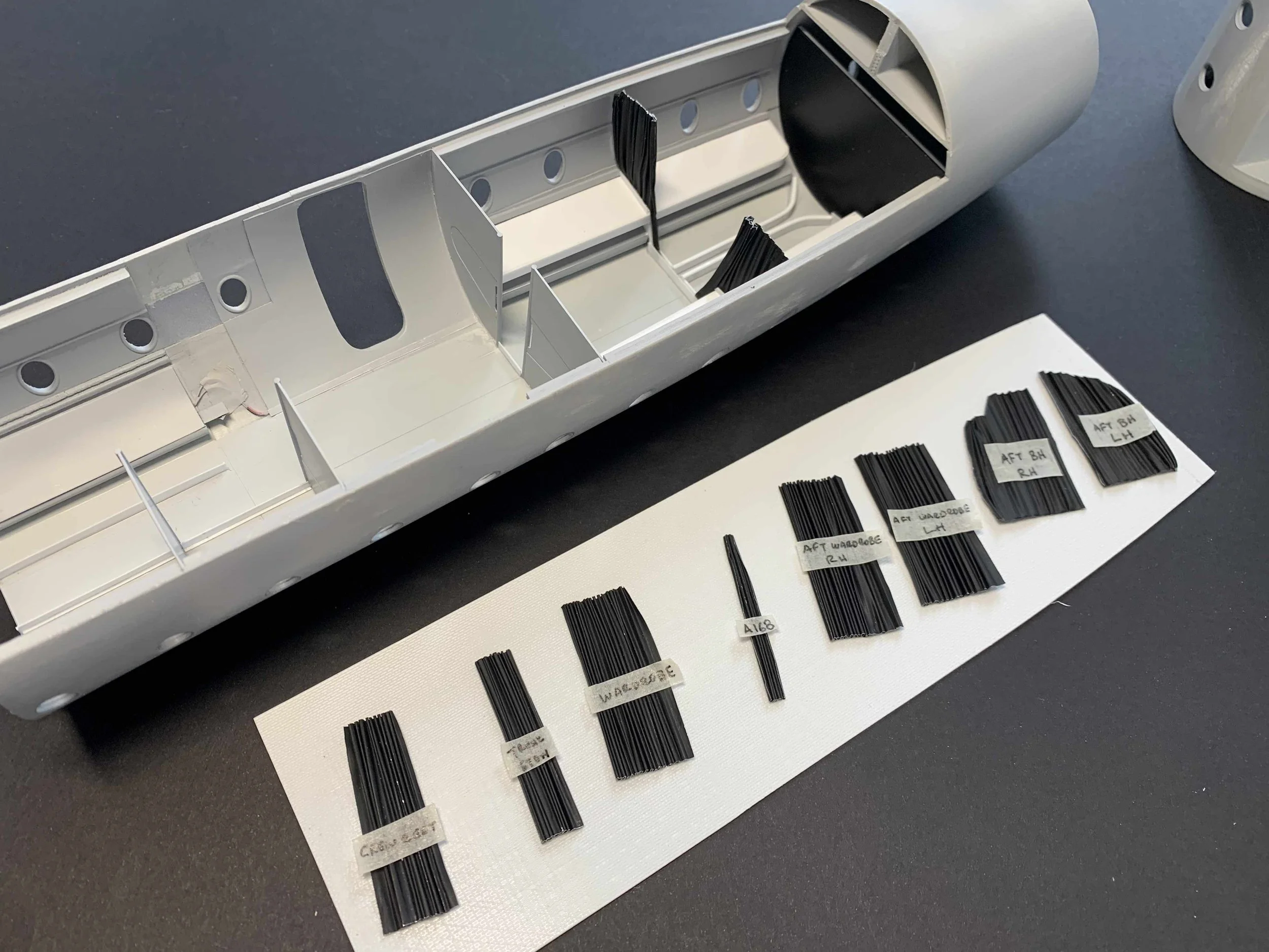
The overhead stowage compartment sections were built with styrene sheet. The ones for the forward cabin had rectangular cutouts made, to allow the fuselage spar frames to pass through (Photo No. 1). Only one section was affixed to the aft fuselage (between Fr.66 and the cocktail bar) because of the installation of the wiring for the aft entry boarding light (See Photo No. 6). There will be two separate circuits in the model as the LED strips are powered by 9 Volts whereas the standalone miniature LEDs are powered by 3 Volts. These circuits will be connected to their respected power sources through the two nose wheels. More details to follow.
The curtains separating the different passenger and crew compartments were crafted using black coated aluminium sheet, simply by folding them with the help of a metal ruler (Photo No. 2). The curtains separating the dinning and rest area had to be trimmed to correspond to the shape of the overhead stowage racks. Curtain rails were also installed at their appropriate locations (Photos No. 3&4).
The partitions were covered with Aviattic wood effect decals and the ones for the aft fuselage were attached to their final locations (Photos No. 5-7). The ones for the forward fuselage will have to be attached after the installation of the passenger seats and crew rest facilities (Photo No. 8).


Cabin Seating
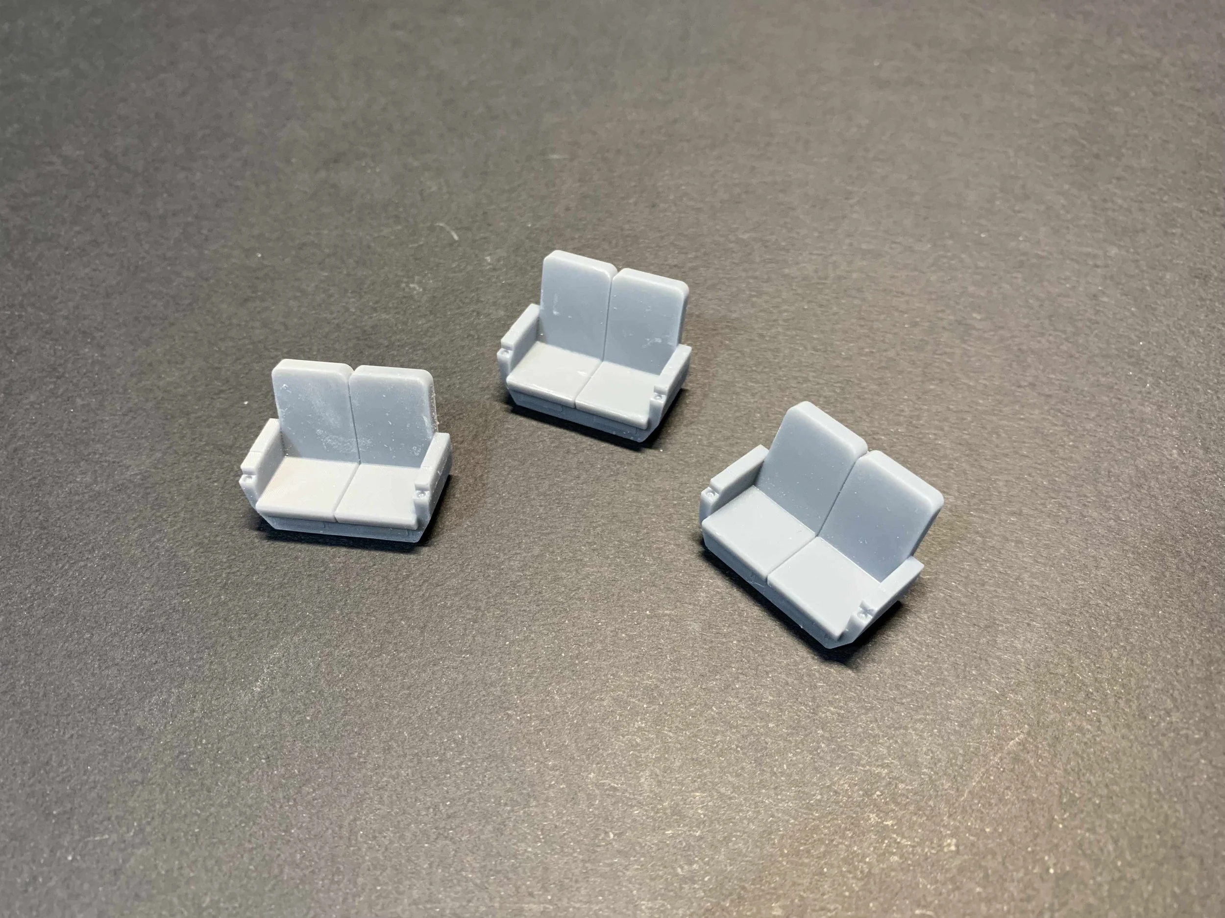
The passenger seats were designed in Autodesk Fusion and 3D printed in resin (Photos No.1 & 2). As there were 11 double seats in this cabin configuration, I opted for the 3D printing option to save myself from crafting one seat and sending it off for resin copies to be made. The rest of the passenger seating was built with styrene plastic that was later ‘upholstered’ with magic sculpt modelling clay. To add to the sense of realism, I refrained from including the headrests in the 3D design in order to make unique individual headrests for each seat. I also scattered a few pillows around, some neatly placed and others less so (Photos No. 7&8). The seatbelts that will be installed at a later stage will also be in line with this principle.


Detailing & Painting
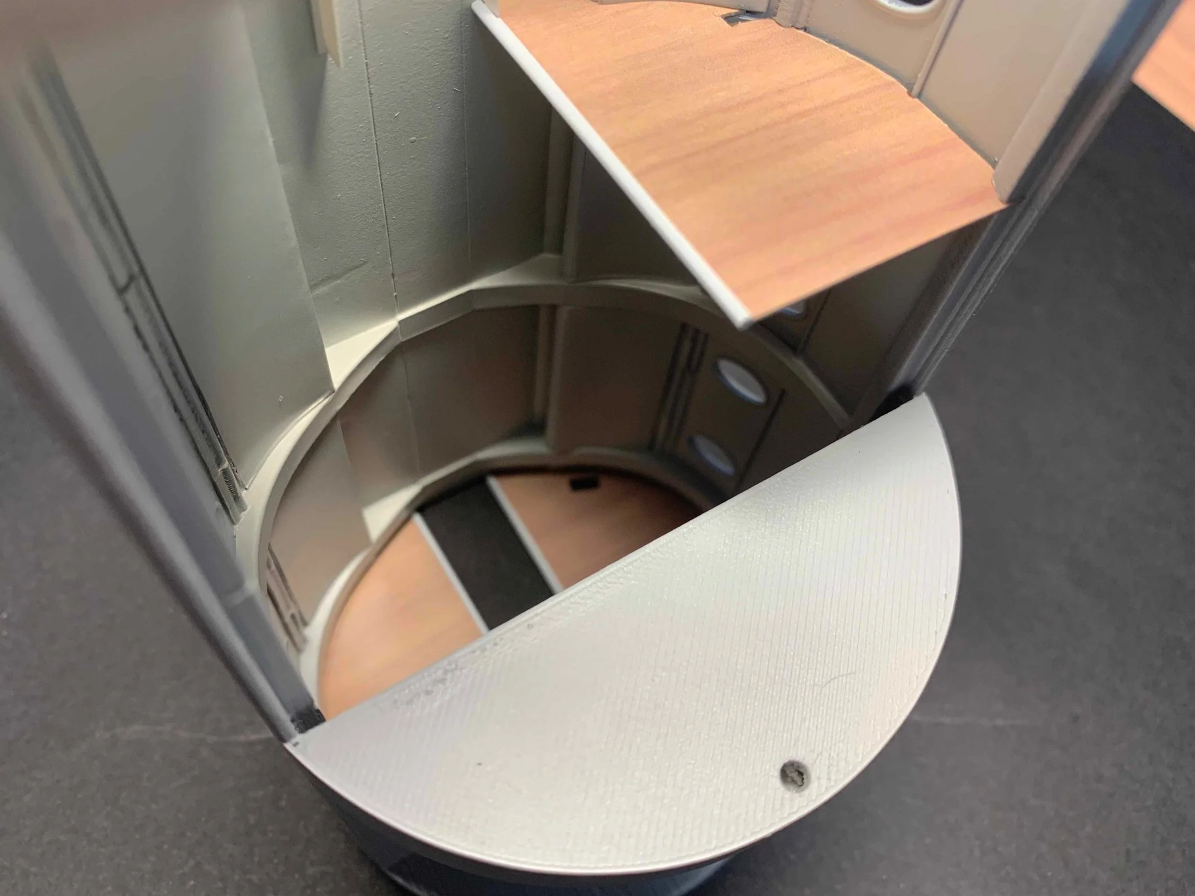
With the majority of cabin equipment either finished or in progress, I decided it was time to liven things up. I started with the window curtains which were printed using a regular laser printer, then carefully folded and installed in the appropriate locations. After a couple of attempts with plastic , I chose to produce the cocktail bar in photo-etched metal alongside my other cabin fittings. It was then painted in the overall cabin interior colour, with its aft side covered in a wood-effect decal. While there is no definitive evidence that this specific aircraft featured the wood effect, it remains highly plausible. Note the recess designed to allow passenger seats to recline into.
The double seats were further detailed using Magic Sculpt, with middle armrests from plastic and seatbelts from pewter, complemented by custom photo-etched buckles in nickel silver. The base color for the seats was selected to be Gunze’s Intermediate Blue, while various details were painted using Vallejo and Citadel colors. The carpet was finished in Tamiya’s Royal Blue and coated with matte varnish.


Passenger Seat Installation
In the following section I will be sharing some useful information on how passenger seats are installed in modern aircraft and demonstrate how this can be represented in scale.
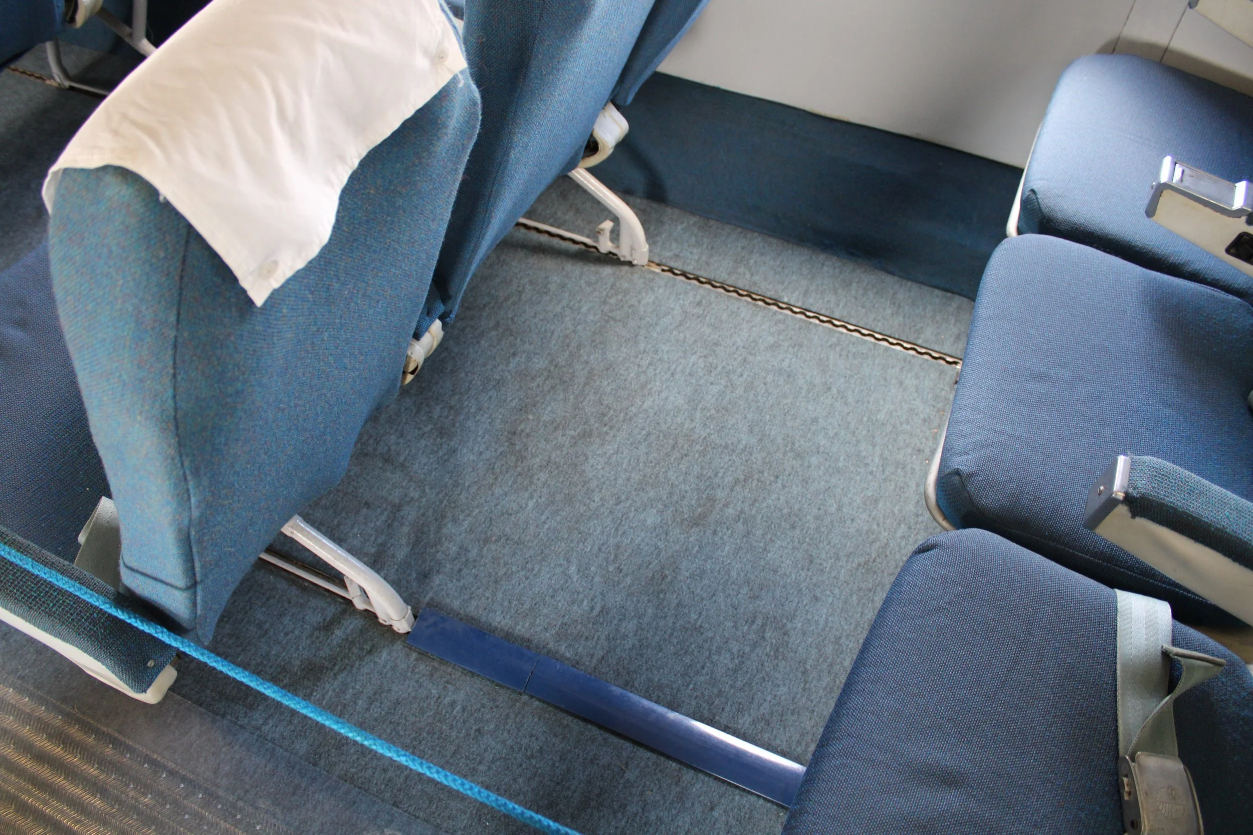
Taken in the Bristol Britannia at IWM Duxford, this image shows the seat tracks on the right and the plastic covers that were normally used to conceal them. The seats would be attached on these tracks at specific distances depending on the intended cabin seating configuration. This system allowed for (and still does) great flexibility of interior cabin layouts. This specific set of seats were not used in operational Britannias, probably donated to the museum from another aircraft. Note the Pan Am logo inscribed on the seatbelt buckle.
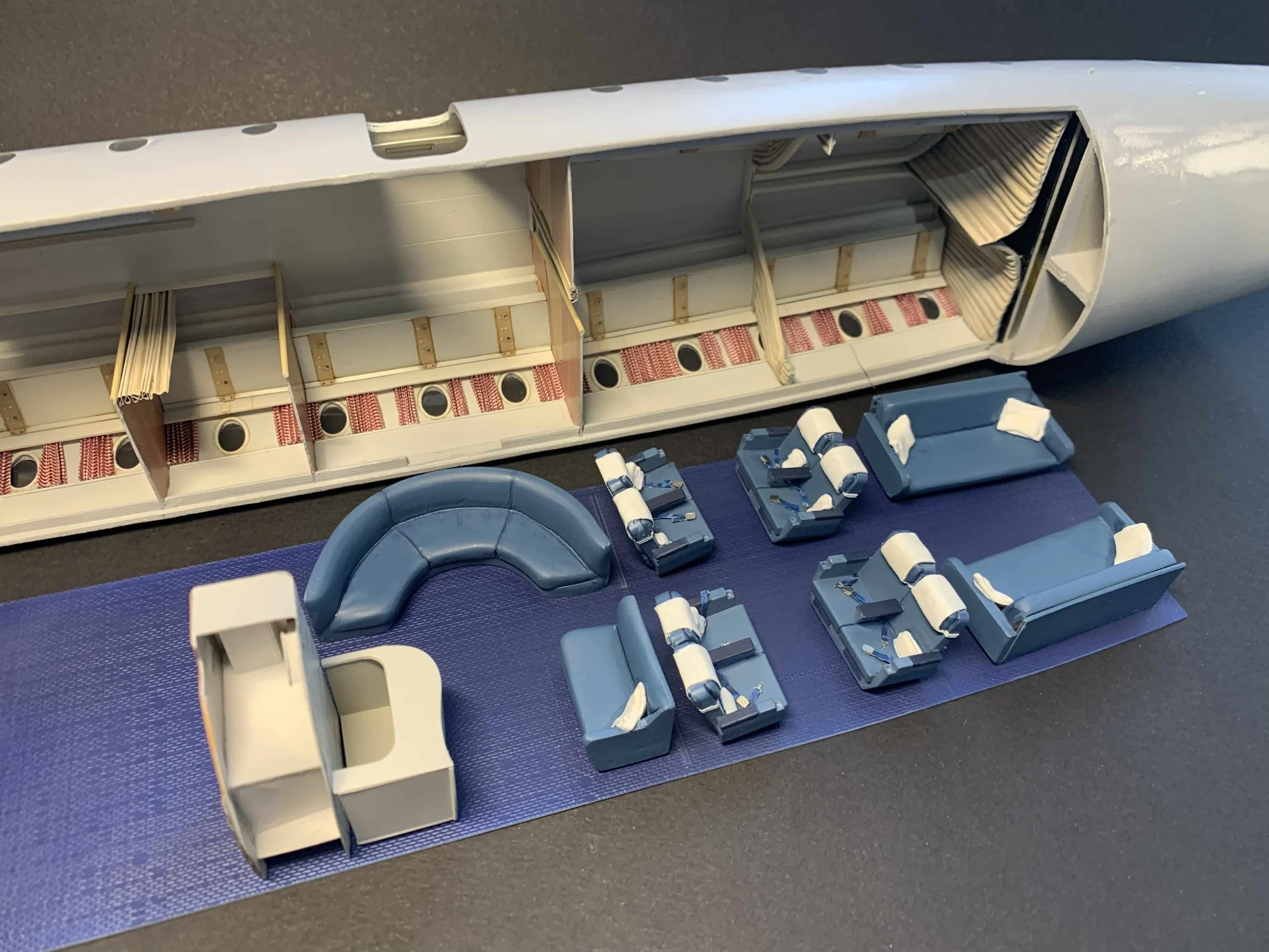
G-ANBG, in its specific VIP configuration, featured three distinct seating sections: the crew rest area at the front, the main cabin with six double seats in the midsection, and the lounge, dining, and rest area at the back. Each section was modelled separately, primarily due to the way the model had originally been designed.
Crew Rest Area - Forward Section
The crew rest area was equipped with two bunk beds, a Vickers Mk.4 single seat, and a folding seat (attached to the lavatory wall) on the port side. On the starboard side, it featured a Microcell twin passenger seat.
The ‘Microcell Ideal’ seat matched the rest of the cabin's seating and was included in the original batch of 3D-printed components. The Vickers single seat, being a one-off, was crafted by cutting a 3D-printed seat in half and modifying it, as shown in the images below. The bunk beds were built using plastic, with all linen sculpted from Magic Sculpt.
To add visual interest, I decided to attach the seats to exposed seat tracks without covers. These seat tracks had been designed and included in my original photo-etched fret. A major advantage of using seat tracks is that they ensure precise seat alignment, given the exact length of the photo-etched tracks both forward and aft of each seat. To further enhance realism, the Vickers seat was painted in different colours—possibly indicating that it had been borrowed from another aircraft or had remained unchanged from before the aircraft’s VIP reconfiguration. Additionally, the bunk bed blankets were painted in a lighter shade of blue to improve the overall aesthetic of the compartment.


Main cabin - Mid Section
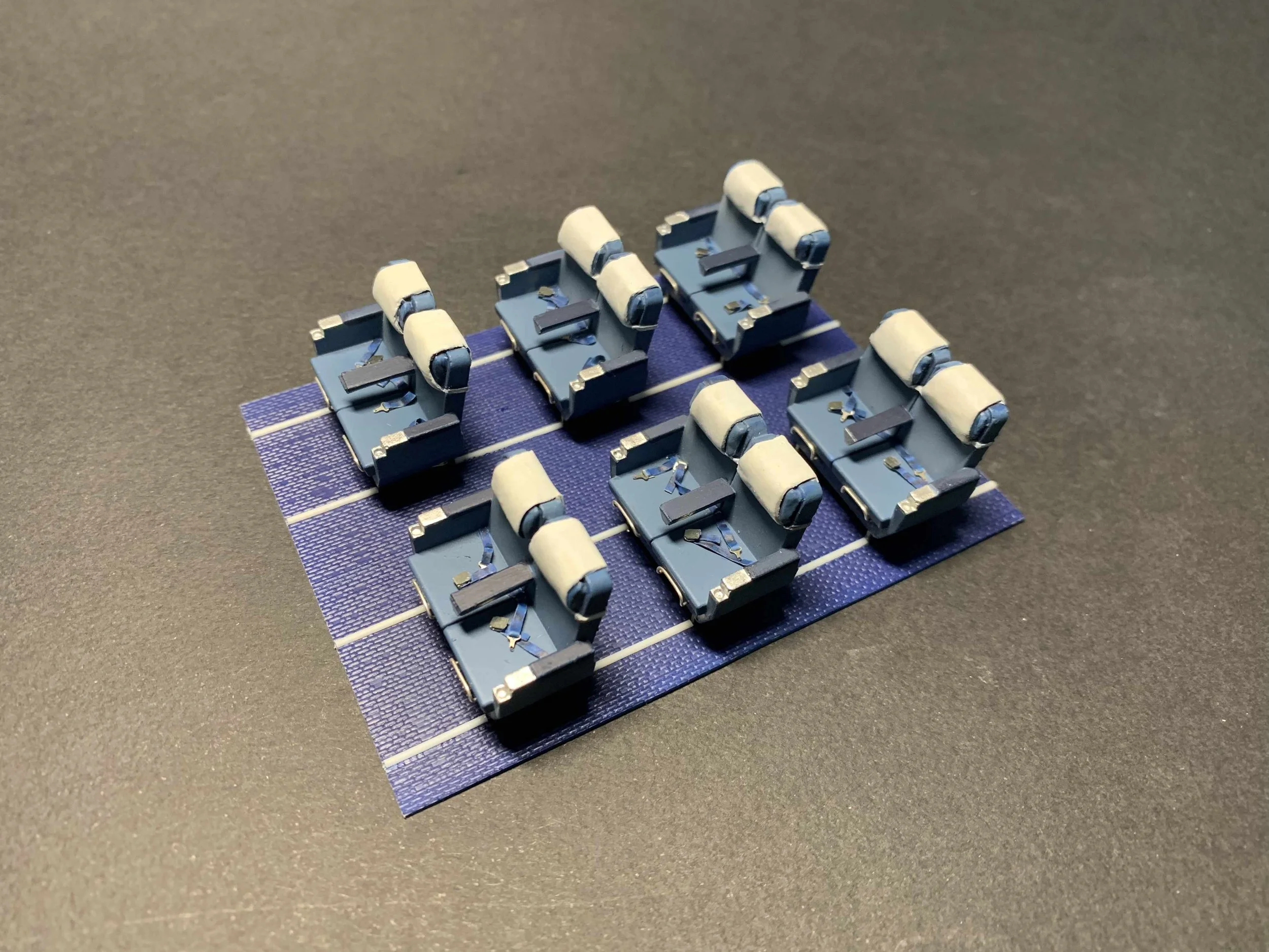
Given its VIP status, it is extremely unlikely that the seat tack covers in the main passenger compartment were not installed or missing. These were therefore represented with equal lengths of half-round Evergreen rod of 1 mm. Starting from the back, each pair of double seats was installed in front of the plastic rods before moving to the next one, as seen in the images below. These were subsequently painted with a similar colour to the carpet.


Aft Cabin
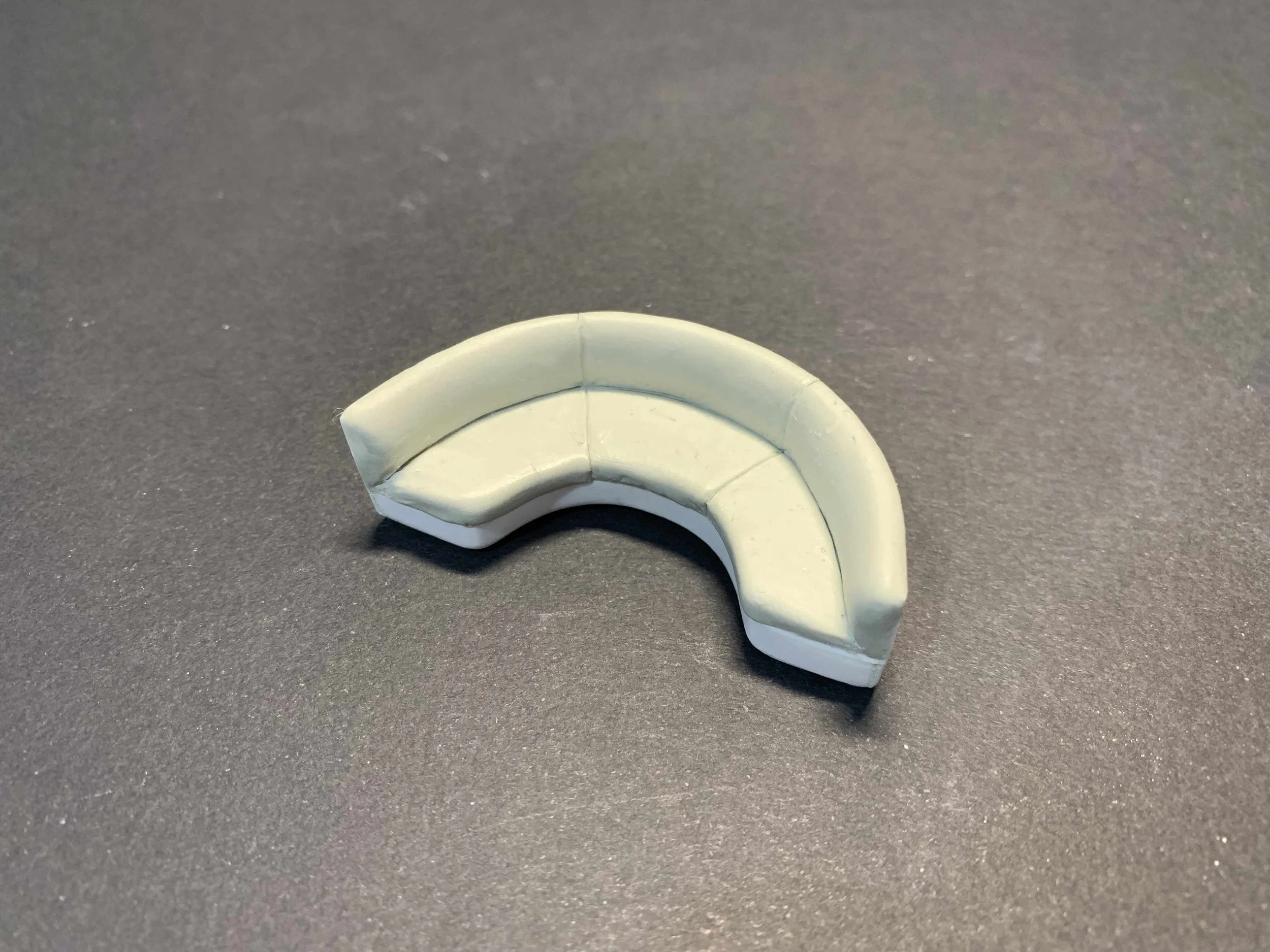
The opposing passenger seats in the dining area were installed in the same way as the main cabin. A couple of ‘settees’ were also installed, along with a small rug made of thin plastic and a footstool of magic sculpt. The bar, divider curtains, and the dining area tables were installed in their appropriate locations in the fuselage.


